| blug | | | projx | | | links | | | about |
Planet generation with OpenGL
A little project I made to deepen my understanding of OpenGL and shaders. It was written in C++.
Generating the sphere mesh
I based my functions on this very detailled article by Peter Winslow. You can check it out if you want more details and explanations on the mesh generation process.
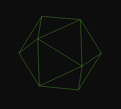
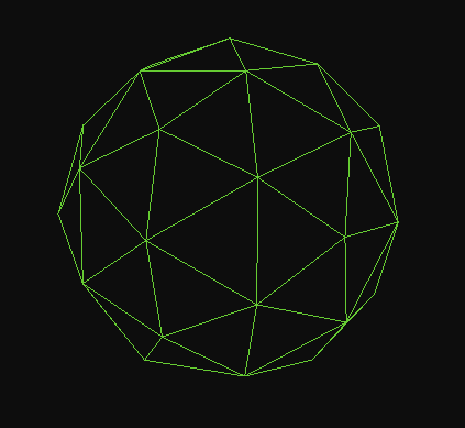
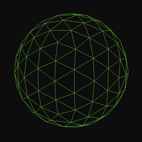
Basically, we first have to generate an ico-sphere mesh (20 triangles) and then subdivide it n times. Subdivision divides each triangle into 4 smaller triangles.
So the code kind of looks like this (I created a Planet class to store everything):
Planet planet = Planet();     // make an empty planet
planet.InitAsIcosahedron();   // initialize the base mesh
planet.Subdivide(2);          // subdivide 2 times
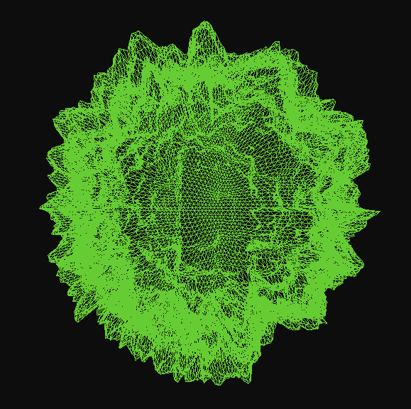
Images are generated with these settings (face culling and polygon mode set to lines):
glEnable(GL_CULL_FACE);
glCullFace(GL_BACK);       // doesn't render back faces

glPolygonMode(GL_FRONT_AND_BACK, GL_LINE);
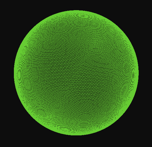
As you can see, we get a rounder and rounder shape with each subdivision.
Unfortunately, the subdivision algorithm is exponentially slower as n grows, making it impossible to generate a mesh at runtime with n >= 7.
So I chose to make a subdivided ico-sphere in Blender, export it as an .obj file and load it in my program with a new Planet.InitAsModel(char *path) function. It uses the Assimp library to load the mesh.
Note: a spherified cube mesh could have also worked.
Applying noise
Since mapping a 2D-noise function over a sphere would be complicated, the idea is to sample a 3D-noise function for each vertex.
We are doing this in the vertex shader. I used this 3D simplex noise shader’s functions.
To apply elevation to the sphere, I first sample the noise value with the vertex’s position vector. Then, since in a sphere a vertex’s position vector is also its normal vector, I add the vector multiplied by the sampled value.
Here’s a simplification of the shader:
#version 330 core
layout (location = 0) in vec3 aPos;

uniform mat4 model;
uniform mat4 view;
uniform mat4 projection;

void main()
{
    vec3 samplePos = aPos + vec3(1.0);

    /* noise parameters are omitted here but used */
    float value = perlinNoise(samplePos * scale);

    vec3 pos = aPos + (aPos * value);

    gl_Position = projection * view * model * vec4(pos, 1.0);
}
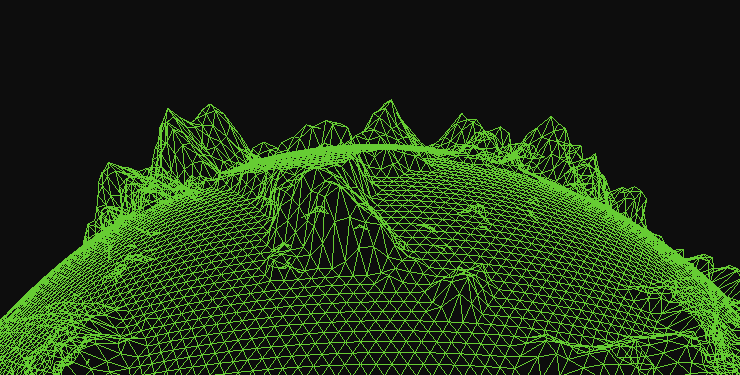
Elevation is applied well, but it needs some tweaking before it actually represents nice planet terrain. A first thing we can do is define a seaLevel threshold variable: this will make the terrain flat if the noise value is under the threshold.
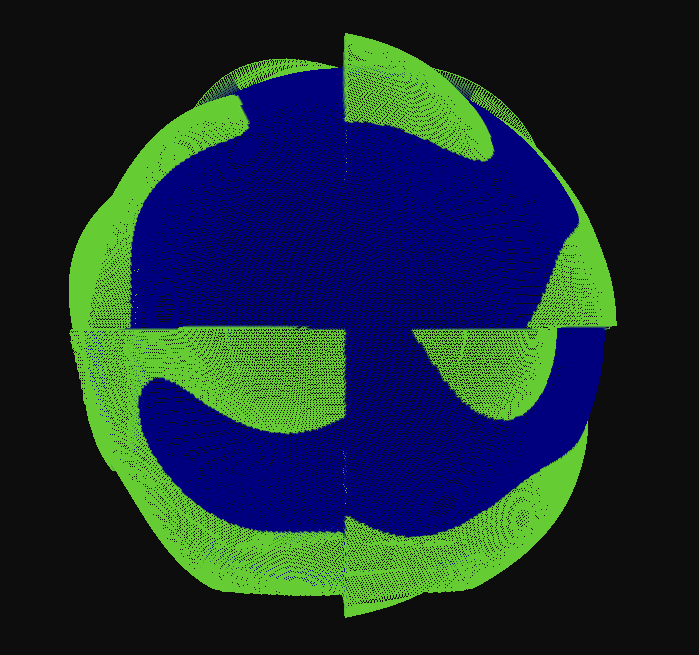
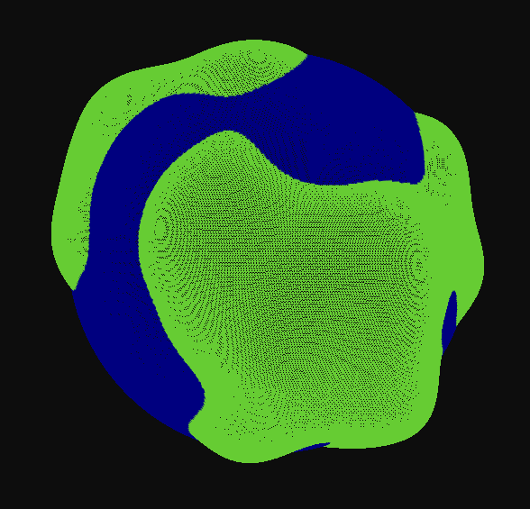
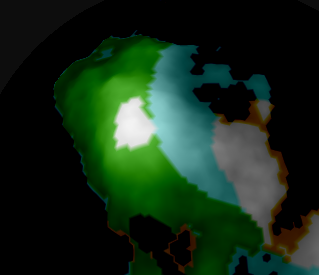
Also note that some vertices have negative coordinates, since the center of the sphere is (0.0, 0.0, 0.0). This resulted in weird cut-offs around the sphere when the scale was small (left screenshot). I fixed this by adding vec3(1.0) to the sample position.
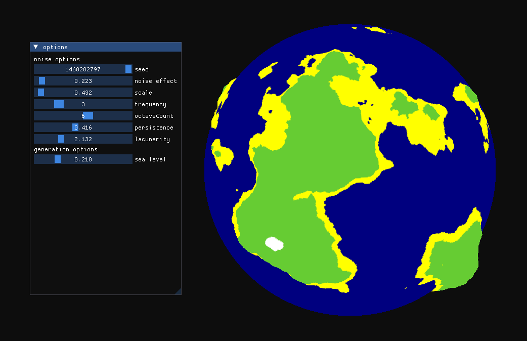
Tweaking and adding color
Now I’m going to use ImGui to make a menu for tweaking noise values. These will be variables sent to the vertex shader as uniforms, which will make editing the planet’s shape faster.
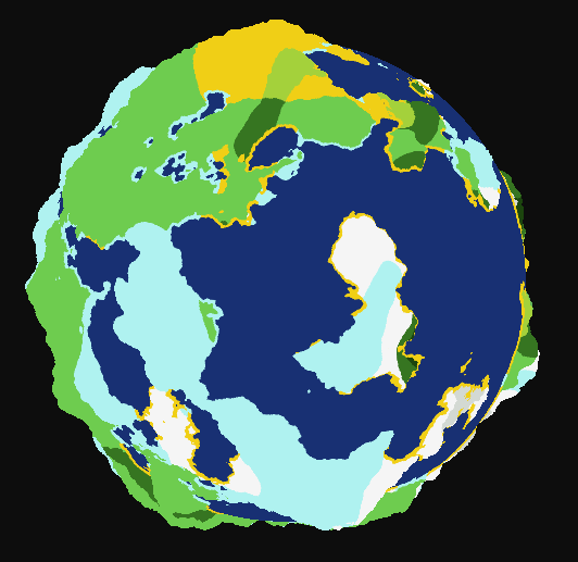
I tweaked the noise parameters a bit, and colored vertices based on their elevation value:
There’s a very good video about Minecraft’s procedural generation in which we can learn that they use multiple noises (instead of only one) for the game’s biome distribution:
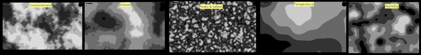
Then, depending on the sampled values, they use a look up table to tell which biome to generate.
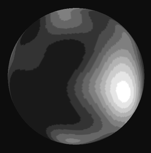
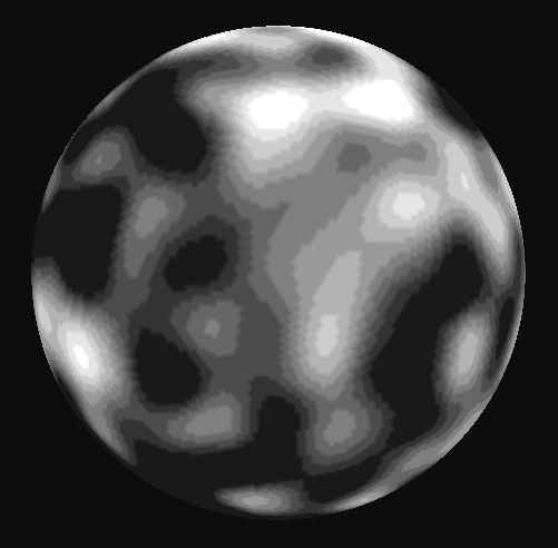
Since their system is very complex, I’m only going to replicate the temperature and humidity noises, and use a bit of elevation information.
I added rules depending on the elevation (sea level, beach level, land level and peak level). If the elevation value is at land level, this is how the biome is selected (humidity from left to right and temperature from down to up):
| Desert | Savanna | Jungle |
| Plains | Forest | Dark forest |
| Ice floe | Snow plains | Snow forest |
Let’s add a little effect to show elevation more:
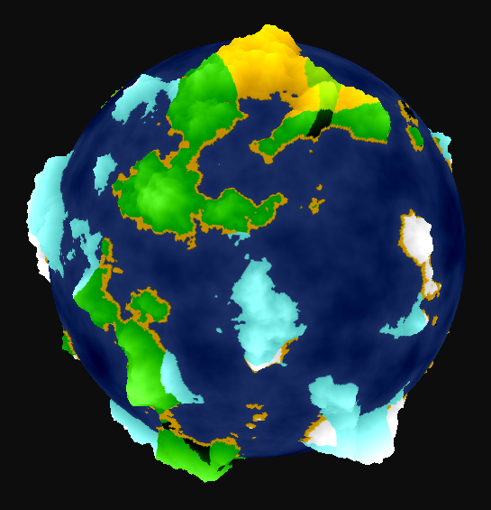
And here we go! Here’s the planet.
One small drawback is that sampling two more noises significantly drops the FPS when using a lot of vertices.
Adding clouds
Then I decided to add clouds. I used the same planet sphere mesh and scaled it up a little. Then, I used a second noise to draw a greyish color if the sampled value is between two cloud_min and cloud_max thresholds.
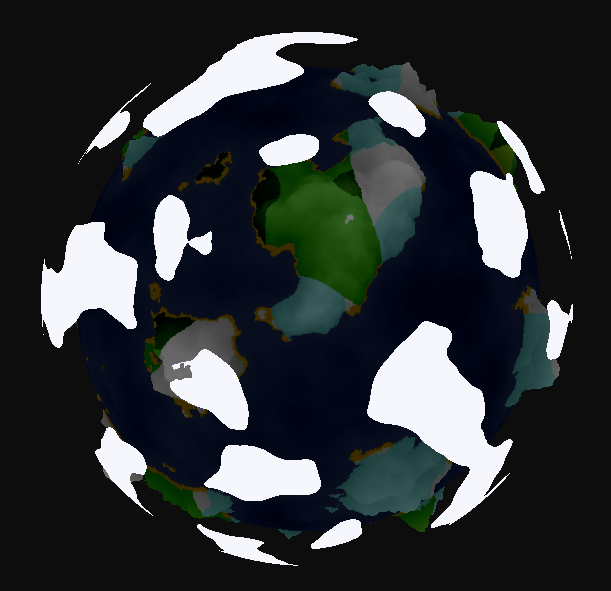
Using a time uniform, I made the clouds move by adding vec3(time * cloud_speed) to the noise sample position.
Doing all of this in the fragment shader obviously costs more than doing it in the vertex shader but it’s ok.